Journal On Camera Latency Measure
Measuring Camera Latency: A Personal Journal
Last week I was experimenting with WebXR and a webcam, and it raised an interesting question for me: how good is the camera latency? After spending another weekend on measurements, I wrote this blog — an incomplete journal on measuring camera latency.
When talking about latency, it’s easy to mix it up with frequency. For example, gaming monitor slogans often say “High Refresh Rate” brings you “Low Latency.” Let’s consider a real-time football broadcast: your friend watches it on a 60 Hz TV on Earth, while you’re watching it on a 1000 Hz TV on the Sun. Your eyes feel much smoother motion than your friend, but your latency is still worse, since the signal takes 8 minutes to arrive at the 1000 Hz TV.
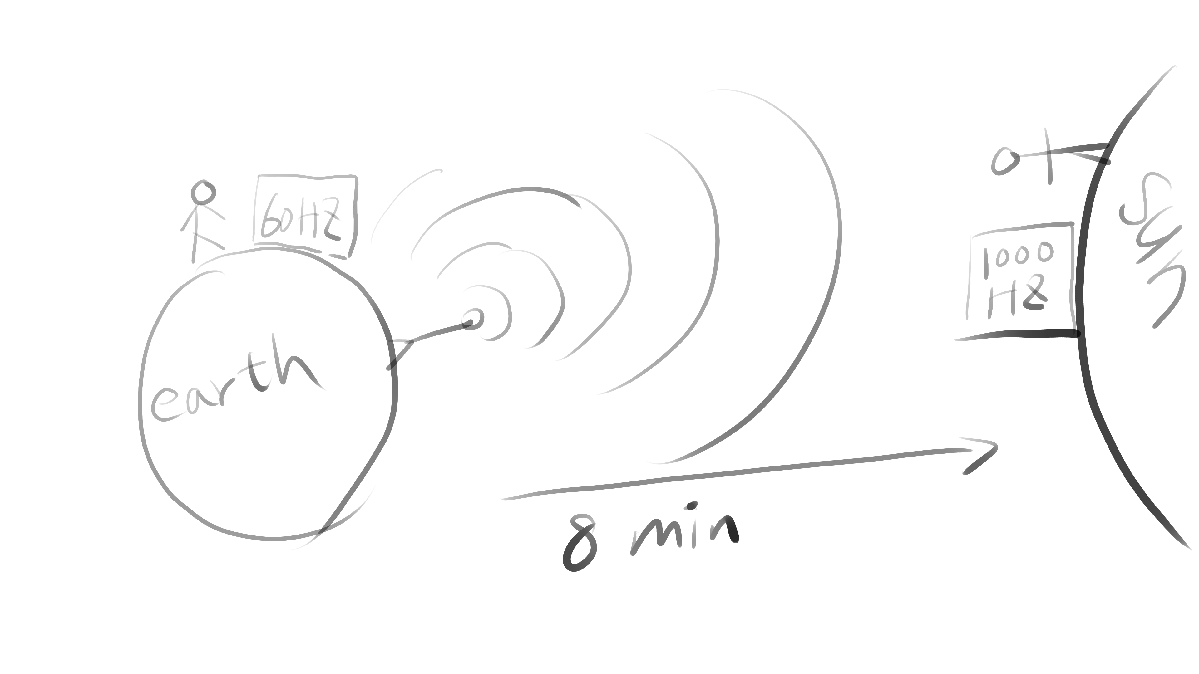
This example shows that frequency only decides how small the time delta is between two signals, while latency means how long it takes the signal to go from the real world to the destination. That’s also why TVs have a “gaming” mode to turn off time-consuming image enhancement algorithms. The refresh rate stays the same, but the latency from digital input to physical output (photons) gets lower.
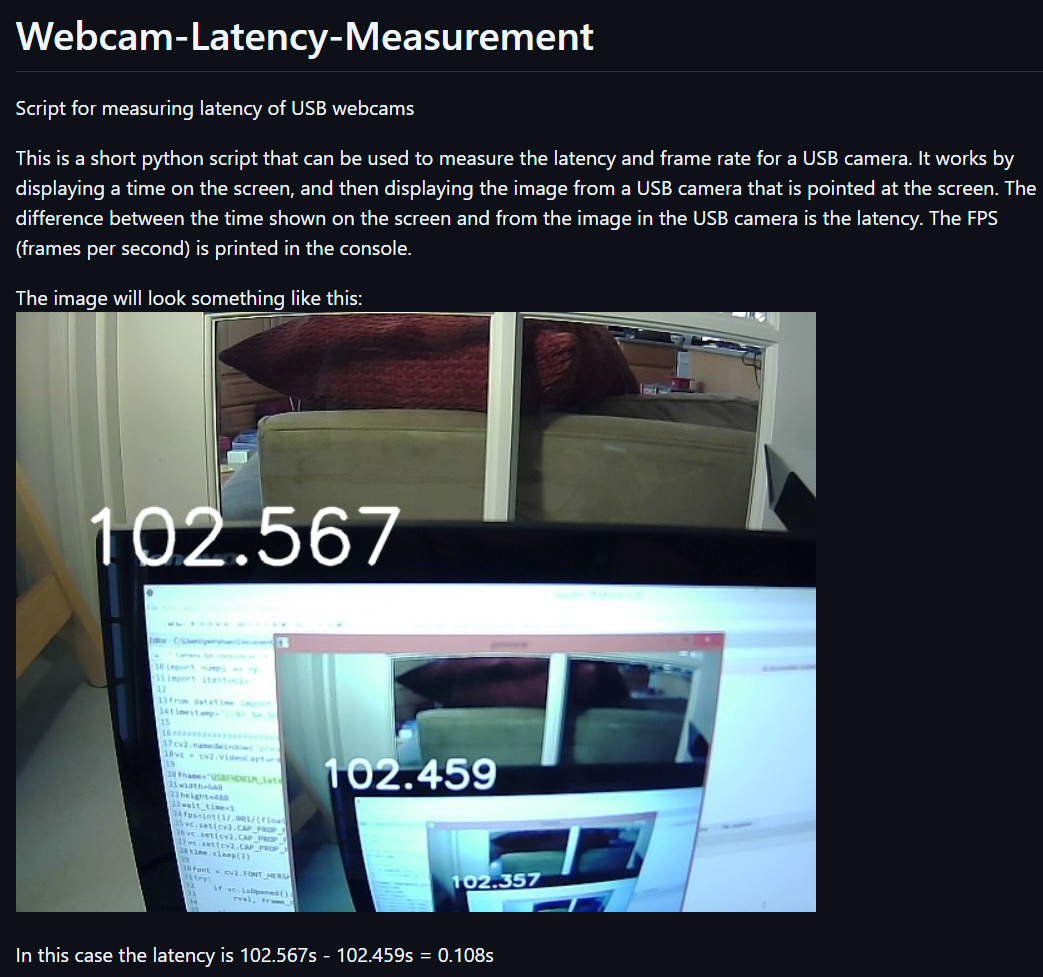
My goal is to measure the time from when the camera shutter finishes reading the image, up to when that image arrives in our application’s memory. Before building my own setup, I first tried a script from GitHub.
The logic is straightforward:
while read camera image
  draw timestamp on camera image
  show this image on screen
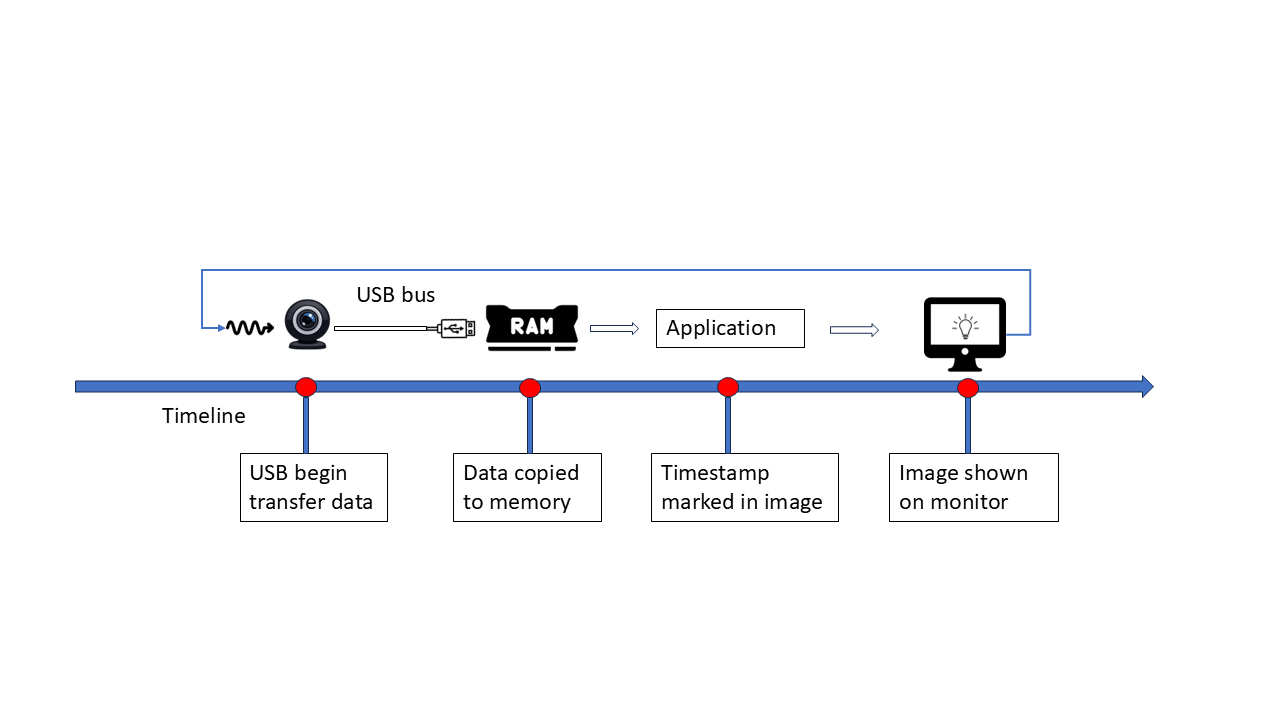
when I tried this script with my webcam (30FPS), I got 32 ms and 36 ms, what interested me was the real-time FPS output: it showed 27.x or 31.x FPS. Seems… Perfectly match the latency? 32 x 31 ≈ 1000 and 36 x 28 ≈ 1000, is this by accident? Let’s draw a diagram to see how blocks connected:
or in another way:
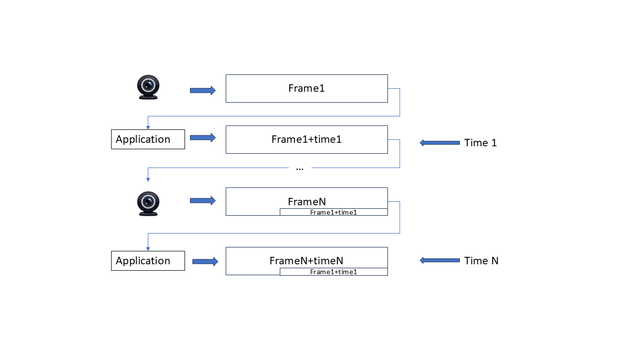
The two timestamps on one image are always the timestamp we mark in the loop, when we calculate the delta between them, of course it’s just the time between two capture time, has nothing to do with the transfer time! The problem is that the ‘start’ timestamp is tied to camera frequency, if transfer latency is lower than that interval, the start timestamp is already out of date (since no camera update happens during that period), So the measured latency precision is also limited by the frame interval.
The original script always give exactly one interval delta on my setup, That’s still useful: It proves that before camera captures the next frame, the previous frame has already been captured and shown on display. No frames are stuck in a queue. Our capture+display logic is fast enough. Otherwise it would mark a none-previous frame with the next timestamp, and the two timestamps in one image would have a delta greater than one interval.
Inspired by that script, we should decouple the start timestamp from camera frequency, and refresh it as fast as possible. My monitor runs at 165HZ, much higher than webcam’s 30 Hz,which should be good enough.
First Try: Console Text
Print updated text in console like this:
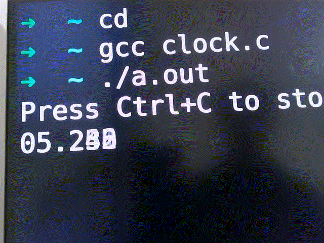
Result: failed, The flushing too fast, camera can’t catch clear text at all
Second Try: Spread text Across the Line
so each timestamp stay stable.
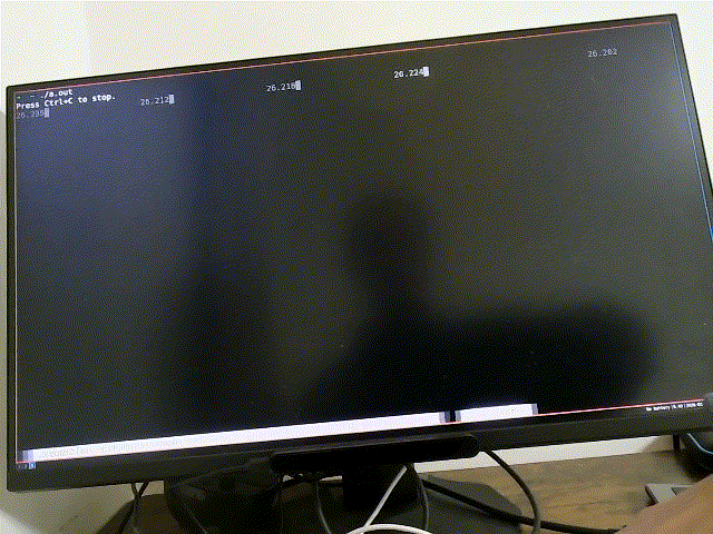
Result: kind of worked, but has problems:
- flushing doesn’t align with V-sync
- App runs under GUI virtual terminal, which may adding buffering latency
- output is controlled by the window manager, hard to reason about queues.
- I have to manually look at each image
Third Try: KMS/DRM + QR Codes
I tried to put Linux into VGA/SVGA mode to avoid KMS/DRM, after some rounds searching with chatgpt/google, I realized such functionality already implemented by graphics card (not monitor), and on UEFI it’s replaced by GOP, also don’t support high fresh rates. So instead I used KMS/DRM directly, it gives:
- Full framebuffer control
- Atomic flip, perfect for to V-sync
- Accurate timing
- OpenGL(ES) support.
There’s also a thin wrapper called SRM that helps start OpenGL(ES) drawing. It assumes the opengl paint callback trigger exactly once between flips, perfectly aligned to V-sync
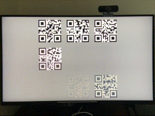
This time I use QRcode to display timestamp, They’re placed in different screen positions and stay for a while. Even at 165Hz, One QRCode can stay longer than 1/165 second. So a 30 FPS camera can capture a stable image. diagram of my latency measure:
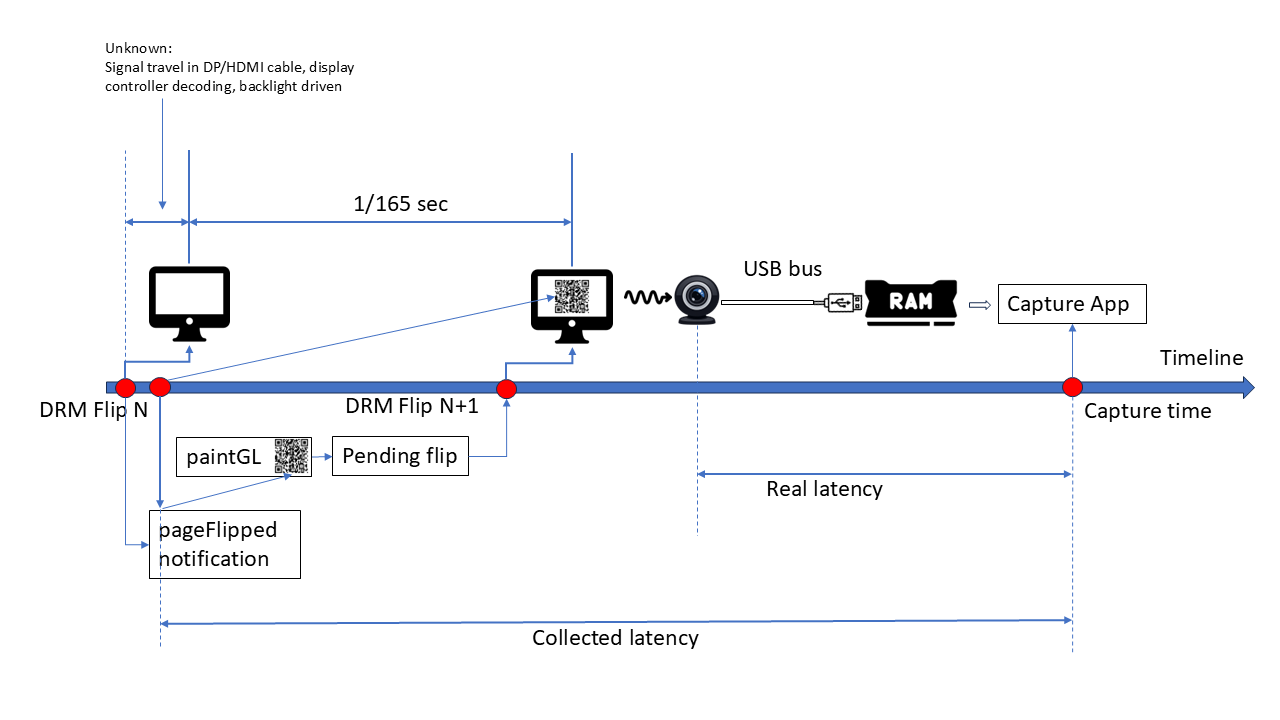
Since there’s still no way to measure the time spend on page flip itself (after we sending flip to kernel, up to the monitor start sending photon for that contents). The best we can do is to use the page flipped callback (of previous frame) timestamp. This will make latency result longer than actual value (1/165 second at most)
I recorded the page-flipped timing:
FPS ≈ 165.0786808021504
And from xrandr
  2560x1440 (0x1c2) 645.000MHz +HSync -VSync *current +preferred
        h: width  2560 start 2568 end 2600 total 2640 skew    0 clock 244.32KHz
        v: height 1440 start 1446 end 1454 total 1480           clock 165.08Hz
FPS = 645000000 / 2640 / 1480 ≈ 165.07985, differences < 1e-5, matches page flip timing well.
OpenGL(ES) QrCode painting logic is written with help of chatgpt, But testing/debugging KMS/DRM application is painful since it takes full control of whole frame buffer (ctrl+alt+FN switching won’t work), so I wrote a GLUT entry to test everything under normal x11 environment, once it’s done, switching to SRM entry just works. Then I used my phone’s 240FPS slow motion recording to verify it :
ffprobe -v error -select_streams v:0 -show_entries stream=avg_frame_rate,r_frame_rate -of default=noprint_wrappers=1 slowmo_clock_boottime.MOV

r_frame_rate=240/1
avg_frame_rate=154080/641 ~ 240.37 FPS
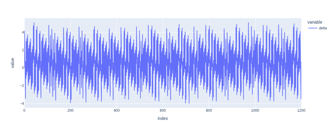
Then I can use its FPS to compare the QrCode timestamp on every frame, Use avg_frame_rate (actual file frame rate) instead of r_frame_rate. Consumer grade slow motion recording usually deployed variable frame rate, 240 is accurate. By aligning start time of both time series, I got following differences:
 ,
,
The small jitter is expected since capture timing doesn’t align with refresh exactly. The slow motion video shows that no more than one new image appear at same time, so now I’m confident to say the KMS/DRM Qrcode flush logic is correct.
Then I disabled dynamic FPS in v4l2
v4l2-ctl --all| grep dynamic_framerate

     exposure_dynamic_framerate 0x009a0903 (bool)   : default=0 value=0

# turn it off by
v4l2-ctl -d /dev/video0 -c exposure_dynamic_framerate=0
Now I captured the screen with my webcam and measured latency:
Best: 32 ms, Worst: 51.5 ms, Avg: 41.2 ms
This data makes more sense, the misalignment between capture and refresh gives the jitter pattern. Note, our result is longer than actual value at most 1/165 sec, so all these values are the “worst case” value. The latency of my webcam should be in range 26ms ~ 51.5ms. Latency came from 2 parts:
- USB transfer time (best case)
- Camera FPS (worst case)
Low FPS Test (10 FPS)
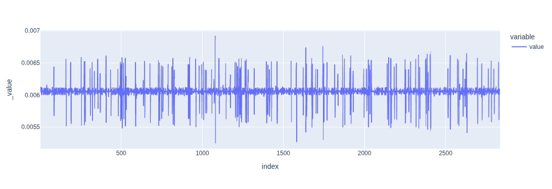
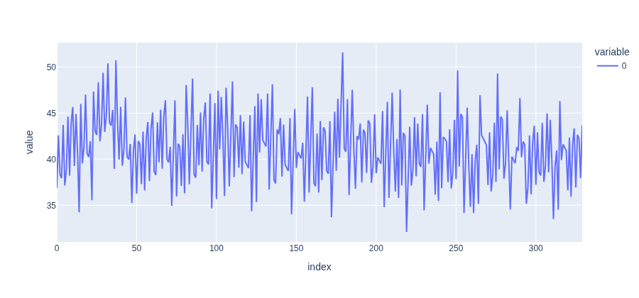
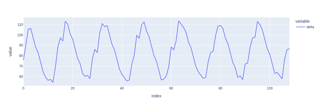
Now let’s verify the latency for low FPS setup. By forcing the FPS to 10, we can predict that original script will always give latency that are 1/10 sec. I made misc changes on original script to paint qrcode instead of text timestamp, Firstly let’s see the delta between two captures time:
 ,
,
Secondly if we compare this timeseries to the delta of two QR timestamp, we will see
capture delta , qrcode delta
 0.1120000000000001,  0.112,
 0.11600000000000055, 0.116,
 0.1120000000000001,  0.112,
 0.11199999999999921, 0.112,
 0.11600000000000055, 0.116,

 ...
 0.11200000000000188, 0.112,
 0.11199999999999832, 0.112,
 0.11599999999999966, 0.116,
 0.11200000000000188, 0.112,
 0.11199999999999832, 0.112,
 0.11600000000000321, 0.116,
 0.11199999999999832, 0.112,
 0.11199999999999832, 0.112
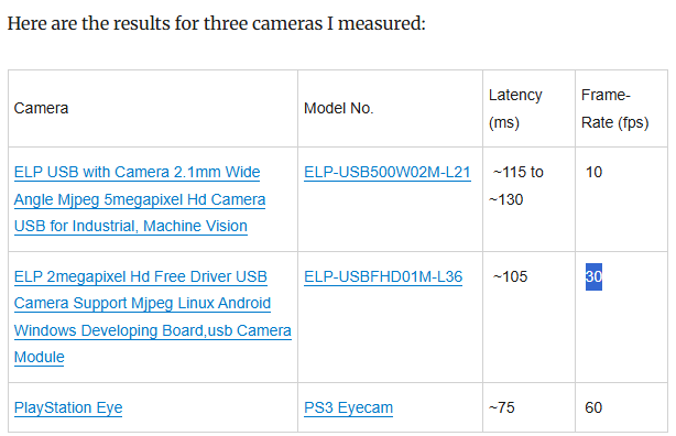
So the original script really measure frame interval, not real transfer latency. Consider a camera that only takes 1 picture every 1 hour, due to the text drawn on image only update once per hour, the latency measured by original script is always an hour. The usb transfer is much faster, but dominated by 1 hour interval time. So Original script result is only meaningful when transfer latency is much longer than one interval period. (it also link to a table of some cameras result, all latencies are greater than one interval)
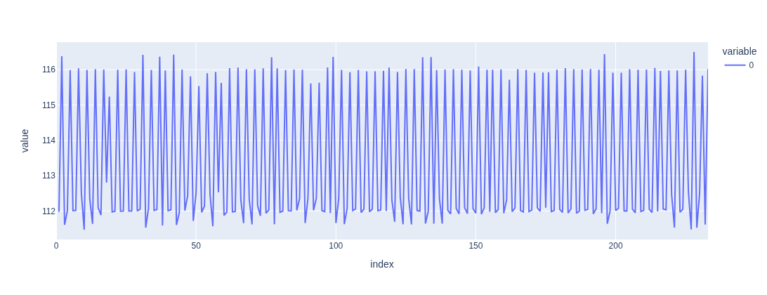
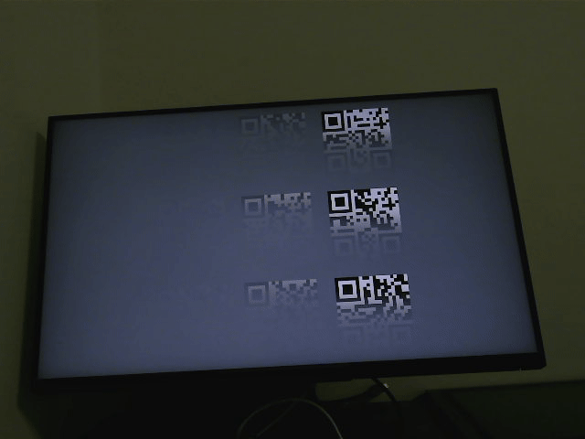
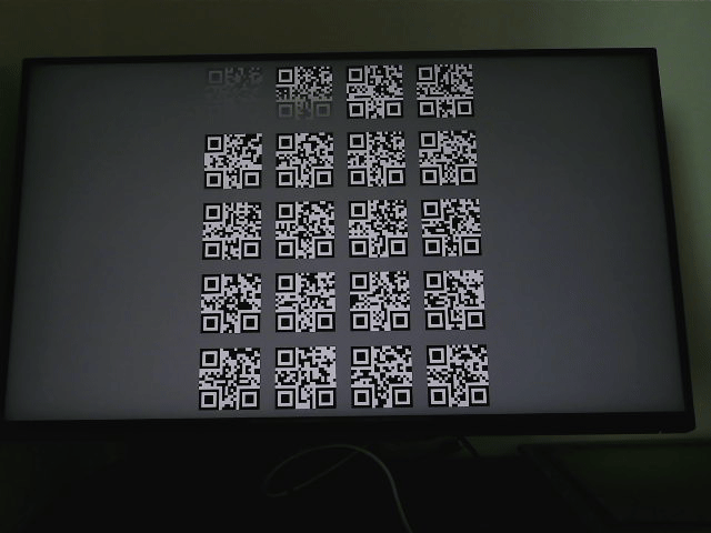
Then measure it with my approach, this time it’s more tricky, since the camera doesn’t work the exactly way at different FPS. For 30 FPS streaming, even camera can’t capture every monitor update, every frame still shows the correct pattern of image: clearest image always appear at bottom right (because we draw new qrcode top-bottom, left-right) but 10FPS is like this:
 ,
,
all qrcode appear/disappear at same time, lead lots of empty image. My suspect is that camera shutter/timer doesn’t work at constant frequency (as capture delta plot shown, it constantly jumping between two period). So I increase the size of qrcode grid, also increasing the stay time of every qrcode, then the capture like this
 ,
,
still not the correct image pattern, but at least no empty image.
 ,
,
Average latency 82.9 ms, best case 53 ms, worst case 113 ms. So latency range should be 47 ~ 113.
Side notes
I also tested with realtime kernel, or switching cpu governor, didn’t see too much changes. Someone said that the usb hub directly to CPU should have lower latency, I tried to connect my webcam to 15b6 (AMD CPU-Integrated, CHIP 0 - LOWEST LATENCY Raphael/Granite Ridge USB 3.1 xHCI, Ryzen 7000/9000 Desktop AM5) and 43fc( AMD Chipset CHIP 1 800 Series Chipset USB 3.x XHCI Controller X870/B850 AM5), also don’t see significant differences.
Nvidia measure E2E input latency using LDAT, Digital Foundry Video shows how it works:
https://www.youtube.com/watch?v=TuVAMvbFCW4